
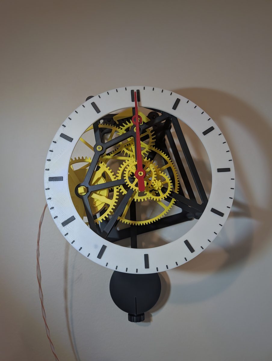
Forget the kit
It started with a Da Vinci clock kit. We went through it properly, and it does not work as drawn. So we dropped it and built our own. The rules:
- Falling weight and a real pendulum
- Wall mounted, 8 to 12 h per wind
- Open skeleton frame, dial ring and hands in front
- Hour and minute hands only
- Every part fits the ~240 mm bed
Gears from our own code
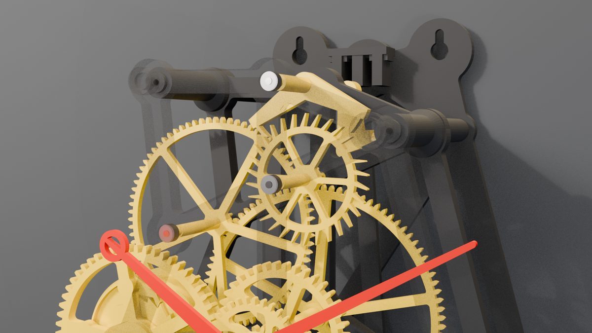
No gear library. We wrote our own cycloidal gear code in OpenSCAD, the tooth shape real clocks use, then the escapement, frame, barrel, motion works, dial and pendulum around it.
A Graham deadbeat escapement with a 30 tooth escape wheel. The drop is 1.5 m. Before anything printed, every gear mesh and the escapement ran in simulation and every part was checked against every other part. Zero clashes. On paper, it was perfect.

Print the truth first
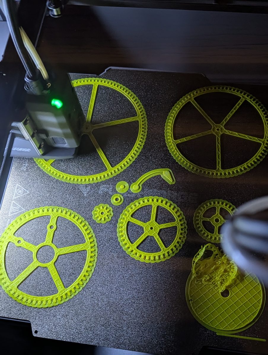
Printed plastic is never the size you drew. Before the real parts: a 13 piece fit gauge. 1h34m, 37.5 g. Bearing pockets, rod bores, and a gear mesh at three spacings.
The gauge settled it. A 3.05 mm bore grips the 3 mm rod. 3.00 had to be hammered in. Gears mesh best 0.1 mm wide.
Black frame, yellow gears
Four heads, four colours. Matte black frame, plates and pendulum. Yellow wheels and barrel for the brass look. Red hands. White dial with black marks.
The dial printed beautifully right up until the end, then the edge lifted. It had been moved off centre for the prime tower, 2 mm from the bed edge, with no brim. An X-Acto blade cleaned it up. The pendulum chops printed on their side, with a ledge over thin air, and turned to spaghetti.
Assembly meets reality
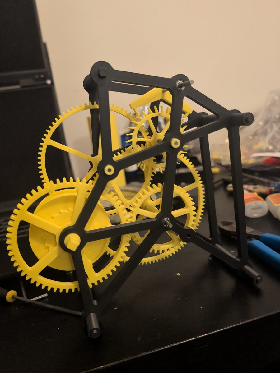
- Three printed pegs snapped. Upright 6 mm pegs, layers across them.
- The barrel rod went in far too tight and the boss broke clean off the back plate.
- The keyholes broke out the top of the backboard.
- The anchor stuck all the time. It was in backwards.
- The click, the pawl that stops the weight unwinding, cammed over centre under load and flipped.
Every one of those went on a list.
It ticks. With a limp.
On 2026-11-08 it ran. One side of the swing was longer than the other, so it was out of beat. We recorded it, measured every tick, and nudged the crutch until the beat was even.
The bob is filled with pink Himalayan salt. 62 g, on a scale I do not trust.
Then it started dying
Stopping at random. Sometimes running through about ten teeth in a burst, like a machine gun. The cause was the lock: how far a tooth lands on the pallet before it is safe. About 0.76 mm is fine on paper. In printed plastic, with real play in every hole, it is not enough.
The worst part: when it was perfectly lined up, it skipped the most. V1 stays whole on the shelf as a keepsake. V2 starts from scratch.
V2: every change has a reason
- Lock too shallow, ran through teethLock about 1.3 mm deep, takes +0.15 mm of print growth
- Frame flexedPlates 8, bars 10, pillars 14 mm
- Printed pegs broke three timesFront plate on 4 x #6 screws
- Barrel tilted under the weightBarrel runs in a front plate bushing with a thrust washer
- Wheels placed by measuring and gluePrinted spacer sleeves set every wheel
- Friction crutch driftedBeat scale on the backboard and a #6 screw beat adjuster
- Keyholes broke outClosed keyholes, movement hangs on 4 board posts
- Rating nut bottomed outRating stud 15 mm longer
- Click v2 worked, but still looked thinClick plane 2.5, was 1.7
- Cannon filed to fit, minute hand fell to 6New cannon with a clear bore and an O-ring
- Dial could pop out at any momentDial sits on 10 x 3 mm magnets
- Bob fill holes too smallFill holes 15, were 8
Plus a twisted hourglass weight and swept spokes on every wheel, because it should look as good as it runs. Halfway through, Windows blocked the slicer, so we switched to our own build of the open source OrcaSlicer. It matched the old one on print time and grams.
The proof test
V3, maybe
On the list, nothing decided: 24 h on one winding, and a minute hand that jumps.